

How To Design A 5th Order Low Pass Unity Gain Active Filter
Previously nosotros described passive low laissez passer filter, in this tutorial we volition explore what is an Active Depression Laissez passer Filter.
What is it, Excursion, formulas, curve?
Equally nosotros know from previous tutorial, Passive depression pass filter works with passive components. But ii passive components resistor and capacitor is the cardinal or middle of a passive depression pass filter circuit. We learned in the previous tutorials that passive low pass filter work'south without any outer interruption or agile response. But it has certain limitations.
Limitations of Passive Low pass filter are as follows:-
- The impedance of the circuit creates loss of the aamplitude. And so the Vout is ever less than the Vin.
- Distension cannot exist done with merely passive low pass filter.
- Filter characteristics are greatly dependable on the load impedance.
- The gain is always equal or lesser than the unity gain.
- More the filter stages or filter order added the loss of amplitude get lesser.
Due to this limitation, if Amplification needed, the best way to add an active component which will amplify the filtered output. This Distension is done by operational amplifier or op-amp. Every bit this requires voltage source, it'south an active component. Thus the name Active low pass filter.
A typical Amplifier draws the power from the external power supply and amplifies the point merely it is highly flexible as we can change the frequency bandwidth more than flexibly. Also, It is user's or the designer'southward choice to select what blazon of agile components to cull depending on the requirements. Information technology can be Fet, Jfet, Transistor, Op-Amp which include a lot of flexibility. The choice of component is also dependable on the toll and the effectiveness if it is designed for a mass production production.
For the sake of simplicity, fourth dimension effectiveness and also the growing technologies in op-amp design, generally an op-amp is used for Agile Filter design.
Let's see why nosotros should choose and op-amp to blueprint an Agile depression pass filter:-
- High input impedance.
Due to high input impedance the input signal couldn't be destroyed or altered. In general or in most cases the input signal which is a very low in amplitude could be destroyed if it is used as low impedance circuitry. Op-Amp got a plus point in such cases. - Very depression component count. Just few resistors are needed.
- Various type of op-amp is available depending on the proceeds, voltage specification.
- Depression noise.
- Easier to design and implementation.
But every bit we know nothing is entirely perfect, this Active filter blueprint also have certain limitation.
The output gain and bandwidth as well every bit frequency response are dependable on the op-amp specification.
Let's Explore farther and understand what is special about it.
Active Low Pass Filter with Amplification:
Before agreement Active depression pass filter design with op-amp, we demand to know a fiddling bit about Amplifiers. Dilate is a magnifying glass, it produces a replica of what we meet but in bigger form to recognize it better.
In the commencement tutorial of Passive low laissez passer filter, we had learned what was Low Pass filter. Low laissez passer filter filtered out low frequency and cake higher i of an AC sinusoidal signal. This Active low pass filter is work in the same way as Passive depression pass filter, just difference is here ane actress component is added, it is an amplifier as op-amp.
Here is the simple Low pass filter design:-

This is the image of Active depression pass filter. Here the violate line shows united states of america the traditional passive low laissez passer RC filter we seen in previous tutorial.
Cutting off Frequency and Voltage gain:
The Cut off frequency formula is same equally used in passive low pass filter.
fc = i / 2πRC
Every bit described in previous tutorial fc is cutting-off frequency and the R is Resistor value and the C is Capacitor value.
The two resistor connected in the positive node of the op-amp are feedback resistors. When these resistors are continued in positive node of the op-amp information technology is called non-inverting configuration. These resistors are responsible for the amplification or the gain.
We tin easily calculate the gain of the amplifier using the following equations where we tin choose the equivalent resistor value according to gain or it tin exist vice-versa:-
Amplifier Gain (DC aamplitude)(Af) = (i+R2/R3)
Frequency Response Curve:
Allow'south meet what volition be the output of the Active Low pass filter or the Bode plot/Frequency response curve:-

This is the terminal output of Agile Low laissez passer filter in op-amp not-inverting configuration. We volition encounter in detail caption in next epitome.

Every bit we see this is identical with Passive low pass filter. From the starting frequency to the Fc or frequency cutting-off point or the corner frequency will start from -3dB signal. The gain is 20dB in this image, so the cut-off frequency is 20dB - 3dB = 17dB where the fc bespeak is situated. The slope is -20dB per decade.
Irrespective of the filter, from the starting point to the cut-off frequency point it is called Bandwidth of the filter and after that, it is called pass band from which the passing frequency is allowed.
We tin can calculate the magnitude gain by converting the op-amp Voltage gain.
The calculation is as follows
db = 20log(Af)
This Af can be the Dc gain nosotros described before past calculating the resistor value or dividing the Vout with Vin.
Non-inverting and Inverting Amplifier Filter Circuit:
This agile low laissez passer filter circuit shown in the showtime likewise has one limitation. Its stability can be compromised if the signal source impedance changed. E.g. decrease or increase.
A standard blueprint practice could improve the stability, removing the capacitor from input and connecting it parallel with op-amp second feedback resistor.
Here is the excursion Non-inverting Active Low pass Filter-

In this figure, if nosotros compare this with the circuitry described in the starting time, we tin can meet that the capacitor position is altered for impedance related stability. In this configuration the external impedance makes no effect on the capacitors reactance, thus the stability improved.
On the aforementioned configuration if we want to invert the output signal then we tin cull the inverting-point configuration of the op-amp and could connect the filter with that inverted op-amp.
Here is the circuitry implementation of inverted active low pass filter:-

It is an active depression pass filter in inverted configuration. The op-amp is connected inversely. In the previous section the input was connected beyond op-amp'south positive input pin and the op-amp negative pin is used to make the feedback circuitry. Here the circuitry inverted. Positive input connected with basis reference and the capacitor and feedback resistor connected across op-amp negative input pivot. This is called inverted op-amp configuration and the output signal will be inverted than the input signal.
Unity Gain or Voltage Follower Agile Low Laissez passer Filter:
Till now the circuitry described here is used for voltage gain and post-amplification purpose.
We tin can brand it using a unity gain amplifier, that ways the output amplitude or gain will be same every bit input: 1x. Vin = Vout.
Not to mention, it is also an op-amp configuration which often described as voltage follower configuration where the op-amp created the exact replica of the input signal.
Let's see the circuit blueprint and how to configure the op-amp as voltage follower and make the unity gain active low laissez passer filter:-

In this epitome, the feedback resistors of the op-amp are removed. Instead of the resistor the negative input pivot of the op-amp connected directly with the output op-amp. This op-amp configuration is called every bit Voltage follower configuration. The gain is 1x. It is a unity gain agile low laissez passer filter. It will produce exact replica of the input signal.
Applied example with Calculation
We volition pattern a circuitry of active low pass filter in non-inverting op-amp configuration.
Specifications:-
- Input Impedance 10kohms
- Gain will be 10x
- Cutoff freq will be 320Hz
Let'due south calculate the value start before making the circuitry:-
Amplifier Gain (DC amplitude)(Af) = (1+R3/R2) (Af) = (ane+R3/R2) Af = ten
R2= 1k (We need to select one value; we selected R2 as 1k for reducing the complexity of the calculation).
Past putting the value together we get
(10) = (i+R3/1)
We calculated the value of the third resistor is 9k.
Now we need to calculate the value of the resistor co-ordinate to the cutting-off frequency. As active low pass filter and the passive low pass filter works on the aforementioned mode the frequency cut-off formula is same equally earlier.
Let's check the value of the capacitor if the cut-off frequency is 320Hz, we selected the value of the resistor is 4.7k.
fc = ane / 2πRC
By putting all value together nosotros become:-

By solving this equitation nosotros become the value of the capacitor is 106nF approximately.
Adjacent pace is to calculate gain. The formula of the gain is aforementioned as passive low laissez passer filter. The formula of gain or magnitude in dB is equally follows:-
20log(Af)
As the gain of the op-amp is 10x the magnitude in dB is 20log(10). This is 20dB.
At present as we already calculated the values at present information technology is the fourth dimension to construct the circuit. Let's add all together and build the excursion:-

We constructed the circuit based on the values calculated earlier. We will provide 10Hz to 1500Hz frequency and 10 points per decade at the input of the active low laissez passer filter and volition investigate farther to run across whether the cutoff frequency is 320Hz or not at the output of the amplifier.

This is the frequency response curve. The green line is started from 10Hz to 1500Hz every bit the input betoken is supplied for that range of frequency merely.
As we know that the corner frequency volition exist always at -3dB from the Maximum proceeds magnitude. Hither the gain is 20dB. So, if we detect out the -3dB signal will go the exact frequency where the filter stops the higher frequencies.
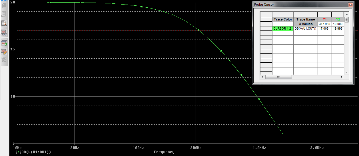
We set the cursor at the 17 db as (20dB-3dB = 17dB) the corner frequency and get 317.950Hz or 318Hz which is close to the 320Hz.
We can alter the capacitor value to the generic one equally 100nF and non mention the corner frequency volition also effected past few Hz.
2nd Order Active Depression Pass Filter:
It'due south possible to add more than filters across one op-amp like 2nd order agile low laissez passer filter. In such case just similar the passive filter, actress RC filter is added.
Let'south encounter how the second society filter excursion is constructed.

This is the 2nd social club filter. In the above figure we can clearly see the two filters added together. This is the second order filter. Information technology is a widely used filter and industrial application is Amplifier, Musical system circuitry before the Power Amplification.
Equally you tin can meet at that place is one op-amp. The voltage gain is same as previously stated using 2 resistors.
(Af) = (1+R3/R2)
The cut-off frequency is

One interesting thing to remember if we want to add together more op-amp which consist kickoff order filters the gain will exist multiplied by each private. Confused? May be a schematic volition help u.s..

The more the op-amp added the more than gain is multiplied. Run across the to a higher place figure, In this image two op-amp cascaded with individual op-amp. In this circuit the Cascaded op amp, If the first one is having 10x gain and the 2nd one is for 5x gain and then the total gain volition be five x 10 = 50x gain.
So, the magnitude of the cascaded op-amp low laissez passer filter circuit in case of two op-amp is:-
dB = 20log(50)
By solving this equation it is 34dB. So the gain of cascading op-amp low pass filter gain formula is
TdB = 20log(Af1*Af2*Af3*......Afn)
Where TdB = Full Magnitude
This is how Active low pass filter is constructed. On the next tutorial, we will see how Active high pass filter can exist constructed. But earlier the next tutorial let's see what the applications of Agile low pass filter are:-
Applications
Active Low pass filter can be used at multiple places where passive low pass filter cannot exist used due to the limitation about gain or amplification procedure. Apart from that the active depression pass filter tin be used in following places:-
Low pass filter is widely used circuit in electronics.
Here are few applications of Active Low Pass Filter:-
- Bass equalization before Power distension
- Video related filters.
- Oscilloscope
- Music command system and Bass frequency modulation likewise as before woofer and high bass sound speakers for bass out.
- Function Generator to provide variable low frequency out at different voltage level.
- Changing the frequency shape at unlike wave from.

How To Design A 5th Order Low Pass Unity Gain Active Filter,
Source: https://circuitdigest.com/tutorial/active-low-pass-filter/
Posted by: gurleygracts1948.blogspot.com
0 Response to "How To Design A 5th Order Low Pass Unity Gain Active Filter"
Post a Comment